A VoIP call that sounds choppy, robotic, or intermittently silent usually has one of two causes: too many packets are being lost on the network, or packets are arriving at irregular intervals — and the endpoint is not compensating well. The second problem is what a jitter buffer is designed to solve. Understanding how jitter buffers work, and what trade-offs they involve, is the first step toward diagnosing and improving audio quality on calls where the codec and bandwidth are both fine but the audio still sounds wrong.
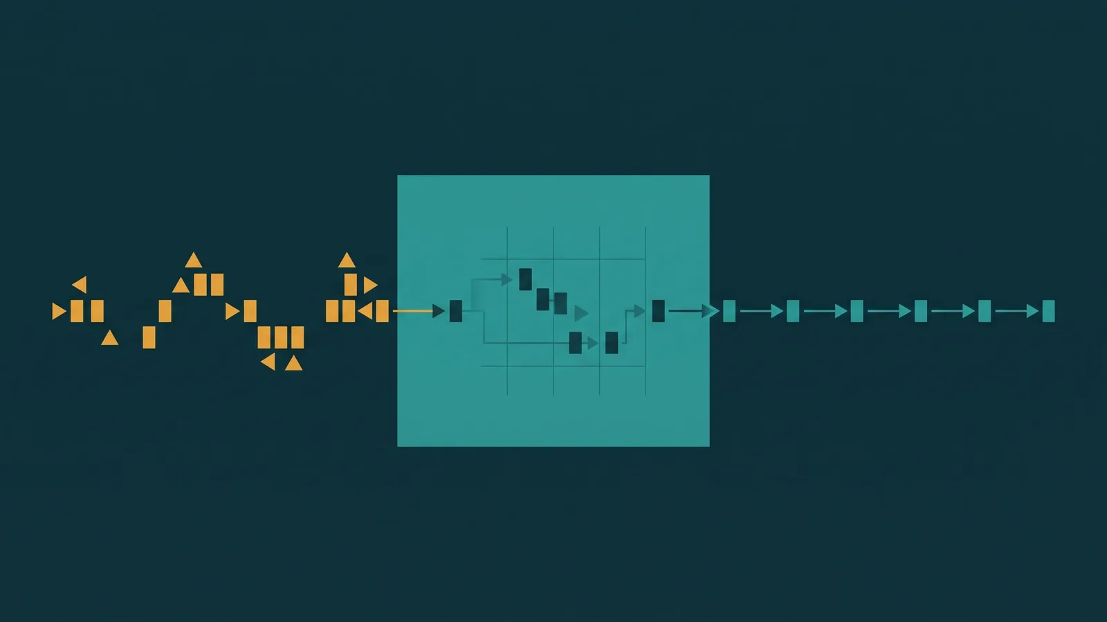
Jitter Buffer Defined: A jitter buffer (also called a de-jitter buffer) is a memory buffer built into a VoIP endpoint — a SIP phone, softphone, or media gateway — that temporarily holds incoming RTP audio packets before playing them back. Packets that arrive early wait in the buffer; packets that arrive late (but within the buffer depth) are still played on time. The result is smooth, evenly-spaced audio playback even when the network delivers packets at irregular intervals.
What Is Jitter in VoIP?
In VoIP, voice audio is digitized and sent as a continuous stream of RTP (Real-time Transport Protocol) packets. Each packet carries a small chunk of audio — typically 20 milliseconds of speech for the G.711 codec, which is the standard PSTN-quality codec used in most business phone systems. On a perfect network, each packet arrives exactly 20ms after the previous one, producing smooth audio playback.
Real networks do not behave this way. Routers queue packets, ISPs reroute traffic, wireless interfaces experience interference, and competing traffic bursts compete for the same links. The result is that packets arrive at irregular intervals: sometimes the next packet arrives in 15ms, sometimes in 40ms, sometimes later. This variation in inter-packet arrival time is called jitter.
ITU-T G.114 specifies that jitter above 30–50ms becomes noticeable to listeners, and jitter above 100ms causes severe disruption to conversational audio. The common causes of jitter in a business VoIP environment include:
- Shared network links: When multiple users or applications share the same uplink, bursty traffic from file transfers, video streams, or backups creates queue depth variation in routers — sometimes called bufferbloat — that delays voice packets unpredictably.
- ISP routing changes: Packets for the same call can travel different paths through the internet on different legs, arriving at different times depending on which route the carrier chose.
- Wireless interference: Wi-Fi retransmissions and collision-avoidance delays add variable timing to packets traversing a wireless segment.
- Router queue depth variation: A router with a large, unmanaged queue can hold some packets briefly while others pass through immediately, creating irregular spacing even on a single path.
Jitter alone does not destroy audio — but if it is not compensated for at the receiving endpoint, the codec has no choice but to play out-of-time packets at the wrong moment or skip them entirely. Both outcomes produce audible artifacts. For a broader look at the factors that affect call quality, see VoIP call quality: what affects it and how to fix it.
How a Jitter Buffer Works
A jitter buffer sits at the receiving endpoint, between the network stack and the audio codec's playback engine. As incoming RTP packets arrive from the network, they are not immediately handed to the codec for playback — they are placed into the buffer first. The codec then reads packets from the buffer at a fixed, regular rate (e.g., every 20ms for G.711), regardless of when those packets actually arrived.
The buffer depth is the key parameter: it defines how many milliseconds of audio the buffer holds before beginning playback. A buffer depth of 40ms means the endpoint waits until it has accumulated 40ms worth of packets before it starts playing audio. From that point forward, it plays out 20ms of audio every 20ms, drawing from the buffer.
Packets that arrive early simply wait in the buffer until their sequence position comes up in playback. Packets that arrive late — but within the buffer depth — still arrive in time for their playback slot. The buffer absorbs the timing variation; the codec sees a smooth, evenly-spaced stream.
The jitter buffer is located at the receiving endpoint — the device playing back the audio. In a two-way call, each endpoint has its own jitter buffer handling the stream arriving from the other party. The caller's phone buffers audio from the agent; the agent's phone buffers audio from the caller. The buffers operate independently and can have different sizes. For more on how audio symptoms relate to network problems, see one-way audio in VoIP: causes and fixes.
Fixed vs Adaptive Jitter Buffer
Jitter buffers come in two types, and the difference between them matters for call quality in real-world conditions.
| Feature | Fixed | Adaptive |
|---|---|---|
| Buffer depth | Constant, set at configuration | Adjusts dynamically based on observed network jitter |
| Response to jitter changes | None — same depth regardless of conditions | Grows when jitter spikes; shrinks when jitter is low |
| Latency added | Constant; always equals configured depth | Variable; minimized when network is clean |
| Risk if configured too small | Late packets are discarded; choppy audio | Buffer expands automatically to accommodate higher jitter |
| Risk if configured too large | Unnecessary latency on every call | Maximum depth still adds latency when buffer fully expands |
| Predictability | High — same behavior every call | Lower — depth varies call-to-call |
| Typical use | Legacy or simple endpoints; controlled network environments | Default on most modern SIP phones, softphones, and UCaaS platforms |
The core trade-off — common to both types — is between protection and latency. A larger buffer depth protects against late packets but adds more latency to every call. A smaller buffer depth keeps latency low but drops more packets when the network is rough. You cannot have both zero late-packet discards and zero buffer-induced latency simultaneously. Every jitter buffer configuration is a point on that spectrum.
Adaptive buffers handle this trade-off more gracefully because they optimize continuously: when the network is clean and jitter is low, the buffer shrinks to minimize latency; when jitter spikes, the buffer grows to protect audio clarity. Most modern endpoints and UCaaS platforms use adaptive jitter buffers for this reason.
Late Packet Discard and Packet Loss Concealment
The jitter buffer can only protect against packets that arrive within its depth window. If a packet arrives after the buffer has already played back the audio slot that packet belongs to, the buffer discards it — it is too late to use. From the codec's perspective, this looks identical to genuine network packet loss: the codec sees a gap in the RTP sequence and has to deal with it.
All modern voice codecs implement Packet Loss Concealment (PLC) to handle this situation. PLC algorithms estimate what the missing audio should sound like based on the audio content that immediately surrounds the gap — essentially synthesizing a best-guess substitute for the lost audio. G.711, G.729, G.722, and Opus all include PLC implementations.
PLC works well when gaps are infrequent and isolated: one or two consecutive missing packets are typically concealed without noticeable degradation. Beyond three to four consecutive missing packets, PLC runs out of reliable estimation range and the audio degrades noticeably — producing clicks, garbling, or silence gaps. This is why persistent packet loss or a jitter buffer that is chronically too small for the network conditions produces audible audio artifacts even when the jitter buffer is technically functioning correctly.
The practical implication is that increasing jitter buffer depth directly reduces late-packet discards — but at the cost of added latency. For a network with consistent 80ms jitter spikes, a buffer depth of 100ms or more will capture most late packets and leave PLC with very little to conceal. A buffer depth of 30ms on that same network will discard a significant fraction of packets, leaving PLC to fill frequent gaps, and the audio will be choppy regardless of PLC quality.
Who Owns the Jitter Buffer
The jitter buffer is implemented in the endpoint that receives the audio — not the platform or carrier in the middle of the call. In a business phone environment, this means:
- SIP desk phones: The jitter buffer is implemented in the phone's firmware. Enterprise IP phones from manufacturers like Polycom, Yealink, Cisco, and Snom expose jitter buffer settings in their admin web interfaces. Consumer-grade desk phones typically do not offer user-accessible buffer settings.
- Softphone applications: The jitter buffer is implemented in the softphone software, influenced by both the application code and the OS audio stack. Mobile softphones on iOS and Android may have additional buffering applied by the OS audio subsystem.
- Media gateways and SBCs: Session Border Controllers and media gateways that process RTP — such as those used in hybrid cloud/on-premise deployments — implement their own jitter buffers for the streams they handle.
- Cloud PBX / UCaaS platform: A cloud platform does not typically apply a jitter buffer for calls transiting through it unless it is performing media processing. For calls where the platform acts only as a signaling proxy and media flows directly between endpoints, each endpoint's own buffer is the only buffer in play.
The location of the buffer matters when troubleshooting. If audio is choppy for calls arriving at a specific type of endpoint — a particular desk phone model or a specific softphone on a particular OS — the problem and its fix are at that endpoint, not in the provider's infrastructure.
Adaptive Jitter Buffer Tuning Guidance
Most platforms and endpoints recommend leaving the adaptive jitter buffer on its default settings unless there is a specific, diagnosed problem. The defaults are calibrated for typical network conditions. Changing them without a clear reason introduces risk. When tuning is warranted, use this approach:
- If calls are choppy or show audio gaps: The buffer is likely discarding late packets. Measure actual network jitter using a tool like ping with large packet counts or a VoIP testing utility. Then increase the minimum or target buffer depth in 10–20ms increments and re-test after each change. Stop when audio is clean.
- If calls have noticeable conversational delay but are otherwise clear: The buffer may be oversized for your network conditions. Reduce the target depth in 10ms decrements and test whether audio clarity holds. Stop reducing when choppiness reappears.
- Do not set the buffer to maximum: Maximum depth eliminates late-packet discards but adds the most latency. Conversations with more than 150ms of end-to-end one-way delay feel awkward — speakers talk over each other and natural turn-taking breaks down. Setting the buffer to maximum solves one problem while creating another.
- Set the right minimum, not the maximum: The optimal buffer depth is the smallest value that produces acceptable audio quality given your network's actual jitter level. Measure jitter, then set accordingly.
- Re-test after network changes: If the ISP link is upgraded, QoS is added, or significant competing traffic is removed, re-evaluate buffer settings. Better network conditions may allow a smaller buffer with less latency.
Jitter vs Jitter Buffer: What You Can Actually Control
The jitter buffer compensates for jitter that has already reached the endpoint. Reducing jitter at the network level is always preferable to depending entirely on the buffer, because lower jitter allows a smaller buffer and therefore lower latency.
Network-level jitter reduction strategies include:
- QoS / DSCP marking: Configuring routers to prioritize RTP traffic using DSCP (Differentiated Services Code Point) markings — typically EF (Expedited Forwarding, DSCP 46) for voice — moves voice packets to the head of router queues. This directly reduces queue-induced jitter caused by competing traffic bursts.
- Adequate bandwidth headroom: A link running at or near full capacity creates queue depth variation. Provisioning at least 20–30% headroom above peak VoIP demand reduces the effect of competing traffic on voice packet timing.
- Wired vs wireless: Replacing a Wi-Fi segment with a wired Ethernet connection eliminates wireless-induced jitter, which is often the largest source of timing variation in small business and home office environments.
- Reducing competing traffic: Segregating VoIP traffic onto a dedicated VLAN or using traffic shaping to throttle non-voice applications during calls reduces the load that causes queue depth variation at the router.
When packet loss persists after jitter is addressed — because the loss is genuine (not late-packet discard) — codec resilience matters. Opus, widely used in WebRTC and modern softphones, has more sophisticated PLC and forward error correction than G.711 or G.729, making it more tolerant of sustained packet loss on difficult network paths. See VoIP call quality for codec comparison and network QoS guidance.